The growing demand for energy has led to the appearance of other energy sources as an alternative to oil. Several technologies that involve using renewable energy, such as wind energy, tidal energy or solar radiation, have been developed.
The use of solar radiation to generate electricity through photovoltaic systems has developed spectacularly over the past five years. This development has been due to various factors, including the maturity of this technology and the financial incentives offered by governments. In any case, this development has led to the emergence of many companies devoted to developing, installing and managing solar parks or farms.
Solar installations have to provide a sufficient return on investment to make them profitable. This will depend on, among other factors, the installations operating perfectly and with optimal performance of the entire plant, especially when the cost of electricity from solar power is higher than the cost of other more conventional technologies.
Table of Contents
Photovoltaic Installations
A photovoltaic installation basically consists of
- Photovoltaic panel systems installed in appropriate structures
- Inverters that convert the direct voltage generated by the solar panels into alternating voltage
- Panel orientation systems depending on the type of installation,
- Wiring, and protection systems, as well as the related medium voltage elements if the system is connected to a commercial network.
All of these elements form a system which, when functioning correctly, will provide a return on the investment within the calculated period.
Photovoltaic Panels
The photovoltaic panel system consists of panels or modules that contain cells based on semiconductors that are sensitive to solar radiation. These cells generate the DC voltage. The technology used in these photovoltaic cells may vary and includes technologies using polycrystalline silicon, thin film, Cadmium telluride or GaAs, each with its own specific output.
These cells are grouped together in the panel in one or several parallel series to achieve the desired voltage and power. Under normal operating conditions, each photovoltaic cell, when it receives solar radiation, generates voltage which, when added to the rest of the cells in the series, provides the output voltage for the panel which will feed the inverter in order to generate the alternating output voltage.
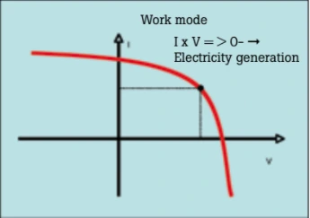
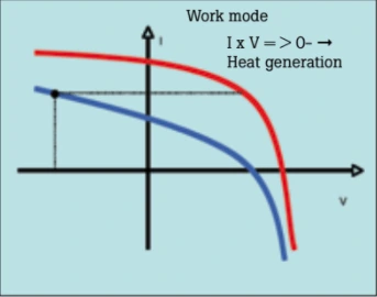
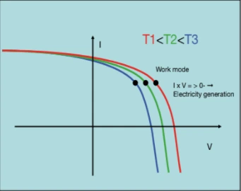
The ratio between the voltage and the current provided by the cell is shown in its characteristic I-V curve. If the cell receives solar radiation, the IxV value will be above zero; in other words, electricity will be generated.
When a cell is not working or is not generating energy because it is not receiving solar radiation, it may be inversely polarised. It will then behave as a charge instead of a generator, which may result in a high dissipation of heat.
Detecting Solar Cells with FLUKE Thermal Imager
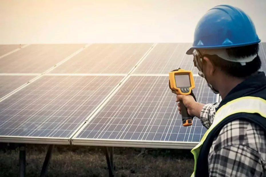
This situation is easily detectable if a Fluke thermal imager with IR-Fusion® technology is used.
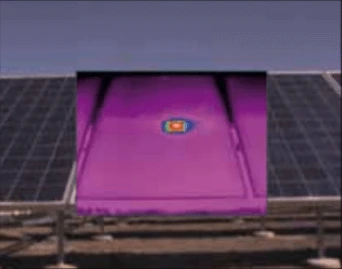
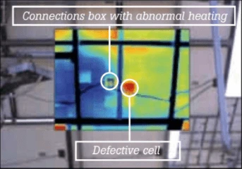
The Fluke thermal imager will simultaneously capture a totally radiometric thermal image together with a visible light image, superimposing them pixel-for-pixel with different degrees of translucency. The image obtained will show the surface temperatures of the objects shown (in this case the photovoltaic panels) using a palette of colours which may be selected by the user and which will represent the different temperatures using different colours, as well as a visible light image that allows the elements to be identified. Thanks to the thermal image, we are able to see how the defective cells are overheating, as shown in the previous image.
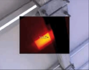
The most favourable conditions for detecting this type of problem are when the panel is providing the most power, normally in the middle of a clear day. Under these conditions cells can be found with temperatures as high as 111oC, as in example.
Depending on the structure of the photovoltaic panel and given that the cells are connected in a series to obtain the most appropriate voltage for the inverter used, a fault in one of the cells could lead to a total or partial loss of power in a photovoltaic panel.
In either case, this type of problem leads to a decrease in the output of the panel, which means that it takes longer to obtain a return on the investment. Furthermore, the problems associated with overheating can lead to the adjacent cells decreasing in efficiency or even breaking down, with the problem spreading across the panel.
How to use FLUKE Thermal Imager?
Photovoltaic panels can be inspected using a Fluke thermal imager from either the front or the back of the panel. The latter has the advantage of avoiding problems connected with solar reflections or reflections on account of the low emissivity associated with the crystalline surface of the panel.
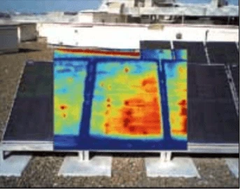
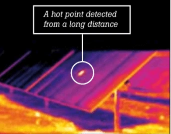
In any case, thermography allows us to identify panels that have hot points quickly and from a distance. We simply have to scan the installation using the thermal imager.
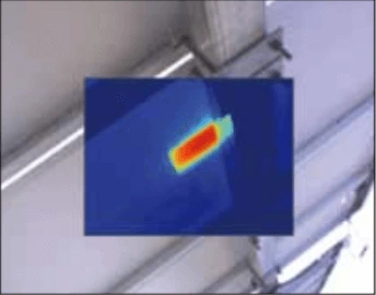
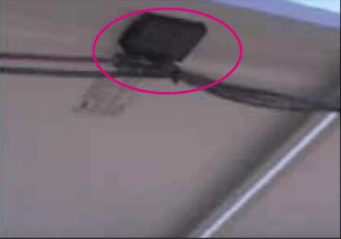
In order to try to avoid the problems associated with the inverse polarisation of cells, photovoltaic modules may include protection diodes (blocking, one-way or bypass), which will dissipate more power the greater the number of defective cells. This heating could also be detected using the Fluke thermal imaging cameras by examining the panel from the side of the connections.
You should pay particular attention to the presence of shadows on the photovoltaic panels caused by trees, medium voltage towers, other panels etc., which may lead to the appearance of irregular thermal areas which result in a false interpretation (especially if the thermal images are taken too early in the morning or too late in the afternoon).
Likewise, you should take the wind into account as it will reduce the temperature of hot points through convection, and they may then not be considered as real faults.
Other elements to be inspected
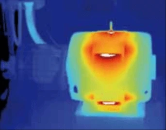
Other areas that can be examined with a thermal imager are motors. Due to various circumstances such as the atmospheric conditions surrounding the motors or whether their dimensioning was incorrect, these motors may heat up to the point that their useful life is significantly reduced. This heating could be caused by mechanical issues (problems in the bearings and alignment), ventilation problems, winding leaks etc.
In order to check that the motor is functioning perfectly, it is extremely worthwhile using other measuring instruments such as clamps for measuring leaks, and insulation meters.
Likewise, we can use the Fluke thermal imager to detect heating problems in inverters and medium voltage transformers. In medium voltage transformers, we can detect problems in the low and medium voltage connections, as well as internal winding problems.
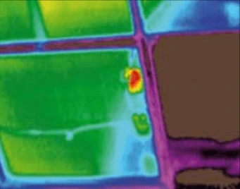
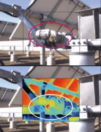
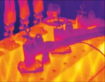
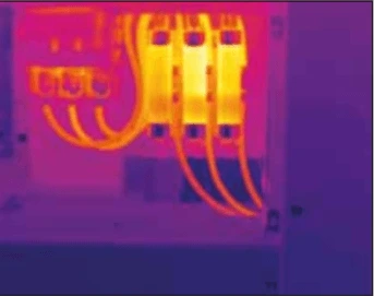
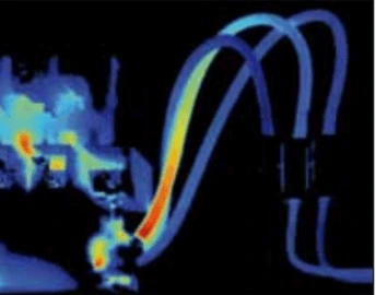
Another area where thermography can be a great help in both preventative and predictive maintenance is the inspection of all of the connection points, which may become loose over time, leading to operational problems and unnecessary breaks, especially given that a photovoltaic plant may have a large number of both DC and AC connections and electric panels. In this respect, it should be borne in mind that a bad connection results in a point of greater resistance; in other words, a point where there will be greater thermal dissipation on account of the Joule effect.
Conclusion
Given the amortisation period of photovoltaic plants (between 6 and 10 years), it is essential to ensure that the output of the plant is within the limits considered during the design phase of the plant so that its profitability can be guaranteed throughout its period of operation. In this respect, thermography is an essential tool for analysing the operation and efficiency of the different elements that make up the installation: photovoltaic modules, connections, motors, transformers, inverters etc. A reduction in the efficiency of the photovoltaic panels can lead to a significant increase in the amortisation period of the plant.
Temperature is a decisive variable in the correct operation of the equipment.
There is a basic rule which states that, for a given piece of equipment, an increase of 10oC above the operating temperature recommended by the manufacturer could lead to a 50% reduction in its useful life.
This simple rule shows us how excessive temperatures can incur significant costs with regard to equipment and general maintenance. Furthermore, if we consider that solar panels are elements that incorporate a large number of semiconductor cells, the heat generated in a defective cell could lead to a deterioration of the neighbouring cells, making the problem worse over time.
Another very important aspect is the success of the plant during the start-up process. In this case, Fluke thermal imager is a very valuable tool as it allows the plant manager to detect photovoltaic panels with manufacturing defects and to refer to the relevant guarantees.
All of these aspects show us how thermography is an essential tool for maintaining installations. Furthermore, the tool is very simple to use, which allows it to be fully integrated into the set of tools used by maintenance technicians (multimeters, clamp meters, leakage clamps, insulation meters, power quality analyzers, etc.).
Sapphire Technologies is an authorized FLUKE distributor in Bangalore & Hosur, Karnataka (India). For more information about Fluke Thermal Imagers or other Fluke instruments in Bangalore, contact [email protected]
