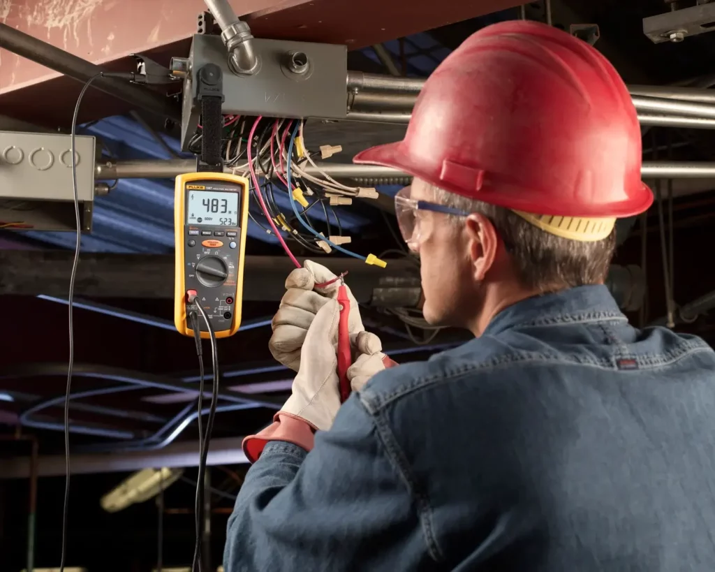
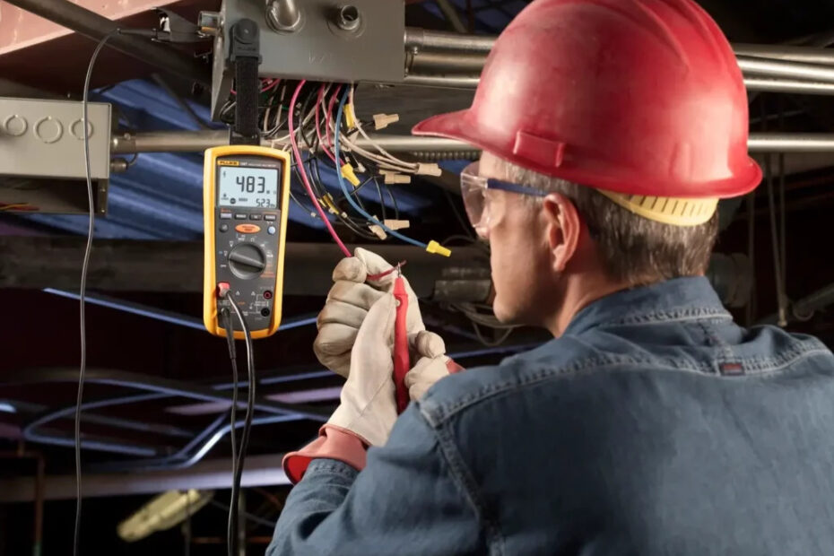
Insulation Resistance Testing is an important way to qualify a new installation. Testing also protects and prolongs the life of electrical systems and motors.
Over the years, electrical systems are exposed to environmental factors such as dirt, grease, temperature, stress, and vibration. These conditions can lead to insulation failure, resulting in loss of production or even fires.
Periodic maintenance tests can provide valuable information about the condition of insulation and help predict possible failure of the system.
Insulation resistance testers, like the Fluke 1520 MegOhmMeter™, available from Graybar, are the ideal tools to determine the integrity of windings or cables in motors, transformers, switchgear, and electrical installations.
Fluke engineers designed the 1520 MegOhmMeter for the most demanding testing jobs. It has a large, backlit LCD with an analog bar graph and digital display plus a last-reading memory display for insulation resistance and Lo-Ohms.
Before Measuring Insulation Resistance:-
In order to obtain meaningful insulation resistance measurements, electricians should carefully examine the system under test. The best results are achieved when:
- The system or equipment is taken out of service and disconnected from all other circuits, switches, capacitors, brushes, lightning arrestors, and circuit breakers.
2. The temperature of the conductor is above the dew point of the ambient air.
3. The surface of the conductor is free of carbon and other foreign matter than can become conductive in humid conditions.
4. Test voltage will not exceed the equipment manufacturer’s maximum test voltage.
5. The system under test has been completely discharged to the ground.
6. The effect of temperature is considered. It is recommended that tests be performed at a standard conductor temperature of 20 °C (68 °F). To measure the conductor temperature, use a non-contact infrared thermometer such as the Fluke 65.
Megohmeters like the Fluke 1520 that have automatic voltage measurement capability can warn you when a conductor is unexpectedly live. An auto-discharge feature helps avoid painful shocks from the voltage stored on equipment capacitance. Agency approvals from UL or others, and an IEC CAT rating of 600 V CAT III or better will insure that the instrument will stand up in a tough electric environment.

Insulation Resistance and Leakage Currents:-
During the testing procedure, the high dc voltage generated by pressing the test button will cause a small (micro-amps) current flow through the conductor and the insulation. For example, the Fluke 1520 has three output voltages: 250, 500, and 1,000 V.
The amount of current depends on the amount of voltage applied, the system’s capacitance, the total resistance, and the temperature of the material. For a fixed voltage, the higher the current, the lower the resistance (E=IR, R=E/I). The total resistance is the sum of the internal resistance of the conductor (small value) plus the insulation resistance in MΩs.
The value of insulation resistance read on the meter will be a function of the following three independent sub-currents.
Conductive leakage current (IL ) is a small (micro-amp) amount of current that normally flows through the insulation, between conductors, or from a conductor to the ground. This current increases as insulation deteriorates and becomes predominant after the absorption current vanishes.
Capacitive charging leakage current (IC ) occurs when two or more conductors are run together and act as a capacitor. This flows as the dc voltage is applied and drops out after the insulation has been charged to its full test voltage.
Polarization absorption leakage current (IA ) is caused by the polarization of molecules within the dielectric material. In most equipment, the capacitive current and polarization current are relatively high and decline over time. This will show up as a low initial megohm reading that steadily increases over time.
Applications of Insulation Resistance Testing:-
When testing the insulation resistance in generators, transformers, motors, and wiring installations, you can employ any of the following predictive maintenance tests. Whether you choose the spot-reading, step voltage, or time-resistance tests depends on the unit under test and the reason for testing.
Proof testing insures proper installation and integrity of conductors. The proof test is a simple, quick test used to indicate the instantaneous condition of the insulation. It is commonly used as part of the “commissioning” process for a new installation. It provides no diagnostic data and is not very useful for predictive maintenance.
For about one minute, a proof test is performed with a single voltage, usually between 500 and 5000 V. It is common to stress the insulation above normal working voltages in order to detect subtle weaknesses in the insulation.
Predictive maintenance tests can provide important information about the present and future state of conductors, generators, transformers, and motors. Examining the collected data will aid in scheduling diagnostic and repair work, reducing downtime from unexpected failures.
During the Spot-reading/short-time resistance test, the megohmmeter is connected directly across the equipment being tested, and a test voltage is applied for about 60 seconds. In order to reach a stable insulation reading in about one minute, the test should only be performed on low-capacitance equipment.
The step voltage test involves resistance testing at various voltage settings. In this test, you apply each test voltage for the same period of time (usually 60 seconds), graphing the recorded insulation resistance. By applying increasing voltages in steps, the insulation is exposed to increased electrical stress that can reveal information about flaws in the insulation such as pinholes, physical damage, or brittleness.
The dielectric-absorption/time-resistance test compares the absorption characteristics of contaminated insulation with the absorption characteristics of good insulation. The test voltage is applied over a 10-minute period, with the data recorded every 10 seconds for the first minute and then every minute thereafter.
The interpretation of the slope of the plotted graph will determine the condition of the insulation. Another method for determining the quality of insulation is to use the polarization index (PI) test. It is particularly valuable for uncovering moisture and oil ingress that have a flattening effect on the PI curve, causing leakage current and eventually shorted windings.
The polarization index is the ratio of two time-resistance readings: one is taken after 1 minute and the other is taken after 10 minutes. With good insulation, the insulation resistance will start low and get higher as the capacitive leakage current and absorption current gets smaller.
Results are obtained by dividing the ten-minute test value by the one-minute test value. A low polarization index usually indicates problems with the insulation.
Testing insulation in electrical systems is a critical step in providing safety and longer system life. The Fluke 1520 MegOhmMeter lets you conduct the test quickly, easily, and safely. For more detailed information, contact us at [email protected]
