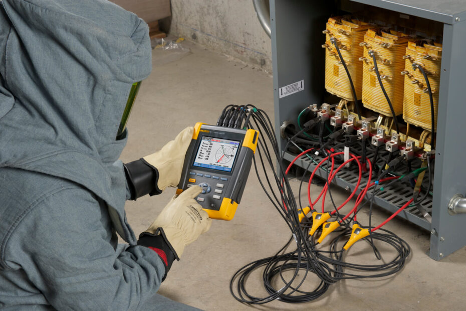
There are hundreds of power quality measurements you can take on electrical systems and equipment. These instructions focus on four predictive maintenance measurements and two power consumption measurements that can help you uncover hidden costs, protect equipment from damaging conditions, reduce unscheduled downtime and improve system performance.
Predictive Maintenance Measurement:-
1. Voltage Unbalance:
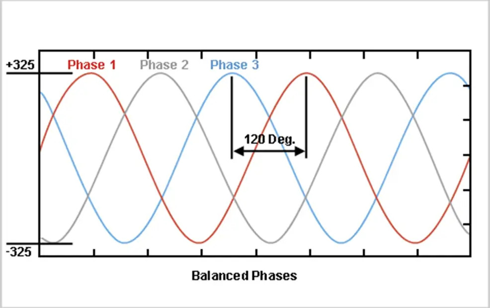
In a balanced 3-phase system, the phase voltages should be equal or very close to equal. Unbalance is a measurement of the inequality of the phase voltages.
Voltage unbalance can cause 3-phase motors and other 3-phase loads to experience poor performance or premature failure because of the following:
- Mechanical stresses in motors due to lower than normal torque output.
- Higher than the normal current in motors and 3-phase rectifiers.
- Unbalance current will flow in neutral conductors in 3-phase wye systems.
Cost of incident:
The major costs are associated with motor replacement (labor + equipment) and lost income due to circuit protection trips.
What to check?
Inputs to motors, VFDs, UPSs1.
How much is ok?
The EN50160 power quality standard requires voltage unbalance, as a ratio of negative to positive sequence components, to be less than 2% at the point of common coupling. NEMA specs call for less than 5% for motor loads. Consult user manuals for other equipment.
How to measure it with the Fluke 430 Series Power Quality Analyzer?
- Connect the voltage leads of the analyzer.
- Configure the analyzer for the appropriate 3-phase power system: delta or wye.
- Select “Unbalance” from the main menu.
2. Total Harmonic Distortion:-
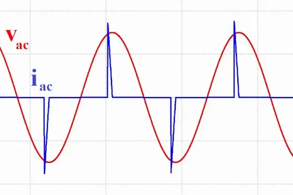
Total Harmonic Distortion (THD) is the sum of the contributions of all harmonics. Harmonic distortion is a normal consequence of a power system supplying electronic loads such as computers, business machines, electronic lighting ballasts, and control systems.
Harmonic distortion can cause:
- High current to flow in neutral conductors.
- Motors and transformers to run hot, shortening their lives.
- Increased susceptibility to voltage sags, potentially causing spurious resets.
- Reduced efficiency of transformer — or, a larger unit is required to accommodate harmonics.
- Audible noise.
Cost of incident
The major costs are associated with shortened life of motors and transformers. If the equipment is part of production systems, income may be affected as well.
What to check?
Motors, transformers, and neutral conductors serving electronic loads.
How much is ok?
Voltage distortion (THD) should be investigated if it is over 5 % on any phase. Some current distortion (THD) is normal on any part of the system serving electronic loads. Monitor current levels and temperature at transformers to be sure that they are not overstressed. Neutral current should not exceed the capacity of the neutral conductor.
How to measure with the Fluke 430 Series Power Quality Analyzer?
- Connect the voltage and current leads of the analyzer.
- Configure the analyzer for the appropriate 3-phase power system: delta or wye.
- Select “Harmonics” from the main menu.
3. Increasing Phase Current:-
As insulation deteriorates it begins to leak. Loads will draw slightly higher current as they age and they may send some of this leakage current into the grounding system. Faults within the equipment may also cause a high ground current. The best way to check insulation is by periodically checking equipment with an insulation tester. But you can also check equipment while it’s in service by monitoring all of the currents (phase, neutral, and ground) to make sure none of these is increasing significantly over time.
Increased phase current can cause:
- Excessive phase currents can further damage insulation and overheat the load, resulting in a shortened life of the load.
- Over-current will cause protection devices to trip, resulting in unscheduled downtime.
- Excessive ground current can create unsafe voltages on metal chassis, cabinets, and conduits.
Cost of incident:
Costs come from premature motor failure and lost income due to over-current protection devices tripping.
What to check?
Any critical load, but especially motors, VFDs, and transformers.
How much is ok?
The nameplate rating of the load should never be exceeded. If you track the phase current being drawn by a load over the months or years, you should be able to get a sense of whether the current is changing.
How to measure with the Fluke 430 Series Power Quality Analyzer?
- Connect the voltage and current leads of the analyzer.
- Configure the analyzer for the appropriate 3-phase power system: delta or wye.
- Select “Volt/Amp/Hertz” from the main menu.
- Press “Save Screen” to record measurements for comparison with future readings.
- Monitor phase current regularly for changes.
4. Voltage Sags:-
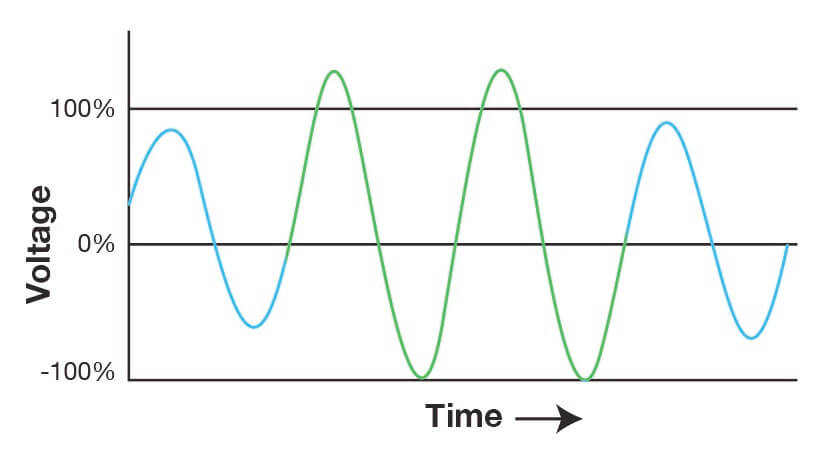
Voltage sags are momentary reductions in RMS voltage for 1 cycle to 2 minutes. Loads may be added without notifying plant management, and these loads may draw down system voltage, especially if they draw high inrush currents. Also, as electrical systems age, the impedance of the system may increase, making the system more prone to voltage sags.
Voltage sags can cause:
- Spurious resets on electronic equipment such as computers or controllers.
- Sags on one or two phases of 3-phase loads cause the other phase(s) to draw higher current in an attempt to compensate. This may trip overcurrent protection.
Cost of incident:
The main cost factors are lost income due to computer reset, control system reset, VFD trip, and shortened life of backup power system‘s UPS due to frequent cycling.
What to check?
Motors, VFDs, UPSs, panels, or PDUs* serving computer equipment or industrial controls.
How much is ok?
Most loads will operate at 90 % of nominal voltage. The ITIC curve suggests that single-phase computer equipment loads should be able to ride through drops to 80 % of nominal for 10 s and 70 % of nominal for 0.5 s.
How to measure with the Fluke 430 Series Power Quality Analyzer?
- Connect the voltage and current leads of the analyzer.
- Configure the analyzer for the appropriate 3-phase power system: delta or wye.
- Select “Dips and Swells” from the main menu.
- Monitor power over time.
- View either as a trend display or event list.
Power Consumption:-
Commercial and industrial power consumers are charged for power consumption based on multiple variables including energy (kWh), peak demand (kW), and power factor. Power quality analyzers can help manage utility bills by determining which loads have a significant effect on peak demand and power factors.
1. Peak Demand:
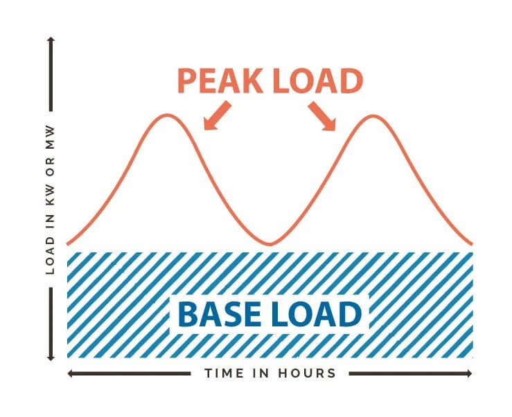
Utilities monitor the amount of power a facility consumes and several times an hour they calculate the average demand for that interval. Peak demand is the highest average demand during all of the intervals in a billing cycle.
Utilities charge based on peak demand because they have to maintain infrastructure large enough to supply power at peak levels. Commercial and industrial customers can manage the high cost of peak demand rates by staggering load cycles to reduce total draw at any one time.
Cost of incident:
This depends on the rate schedule of the utility. It may be higher during the summer months and at certain times of the day.
What to check?
- Find out what demand interval the utility uses — 15 minutes is common.
- Measure demand overtime at the service entrance.
- Look for significant loads operating concurrently and use demand measurement to verify readings for the individual loads.
How much is OK?
There are no safety or regulatory limits other than what the facility can afford.
How to measure it with the 430 Series Power Quality Analyzer?
- Connect the voltage and current leads of the analyzer.
- Configure the analyzer for the appropriate 3- phase power system: delta or wye.
- Set the demand interval to correspond to the one specified by your power utility. Press Setup, Function Pref (F3). Select “Power & Energy” from the Select Function menu. Arrow down past the bottom of the screen until “Demand int” is highlighted.
- Select “Power & Energy” from the main menu and monitor the power for as long as necessary.
- Use the trend display to see the peak demand. The cursor will help you see the demand at any time during the recording.
2. Power Factor or Reactive Demand:-
Power factor compares the real power (watts) being consumed to the apparent power (Volts-Amps) of the load. A purely resistive load would have a power factor of 1.0.
The power available to perform work is called real power (kW). Inductive loads such as motors, transformers, and high-intensity lighting introduce reactive power (kVARs) into a power system. The system capacity is rated by the apparent power (kVA) which must be large enough to accommodate both the real power (kW) and reactive power (kVAR). Since reactive power requires system capacity but performs no work, utilities and plants try to keep net kVARs low. High reactive power translates to a low power factor.
- Utilities may charge higher rates or penalties for low power factors or high VARs.
- System capacity restrictions cause voltage drops and overheating.
- Inductive VARs can be corrected by applying capacitors or active conditioners.
What to check?
- See if your utility rate plan imposes a charge for reactive demand or power factor.
- Find out how the utility measures power factors or VARs. For example, are they looking at peak intervals or averages?
- Identify loads that are causing lagging reactive power and develop a strategy for power factor correction.
How much is OK?
To avoid paying higher utility fees, power factor should be higher than .97. Capacitors may be applied on individual loads, at a confluence of several, or at the service entrance to improve the power factor.
Cost of incident
This varies. Some utilities charge a rate for every percentage point between .85 and .97. Some charge a rate based on the number of VARs you use. Some don’t charge at all.
How to measure it with the 430 Series Power Quality Analyzer?
Start at the service entrance, where the utility takes its data, and then check individual loads or transformers.
- Connect the voltage and current leads of the analyzer.
- Configure the analyzer for the appropriate 3-phase power system: delta or wye.
- Set the demand interval to correspond to the one specified by your power utility. Press Setup, Function Pref (F3). Select “Power & Energy” from the Select Function menu. Arrow down past the bottom of the screen until “Demand int” is highlighted.
- Select “Power & Energy” from the main menu and monitor the power.
Measuring the lowest power factor for a demand interval: Press F4 Trend and then press F1 to toggle through the parameters until PF is displayed.
Measuring average power factor: Take the ratio of kWh/kVAh to get the average PF over the recording period.
Wrapping it up
The new Fluke 430 Series Power Quality and Energy Analyzers offer the best in power quality analysis while also introducing, for the first time ever, the ability to monetarily quantify energy losses. In addition, you can now identify your facility’s high energy usage and pinpoint specific areas of improvement to reduce both monthly costs and carbon emissions.
Sapphire Technologies is an authorized Fluke distributor in Hosur & Bangalore, Karnataka. To explore the range of Fluke power quality analyzers or other Fluke test & measurement products, contact us at [email protected]
