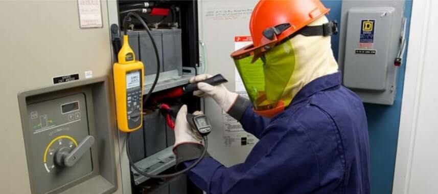
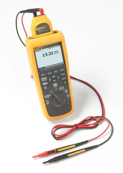
Standby battery backup systems or Fluke Battery Analyzer play a critical role in keeping essential operations functional in the event of a utility outage.
Facilities like data centers, hospitals, airports, utilities, oil and gas facilities, and railways can’t operate without 100% backup power reliability. Even standard commercial and manufacturing facilities have backup power systems for their emergency systems, alarms and controls, emergency lighting, steam, and fire control systems.
Most backup power systems use an uninterruptable power supply (UPS) and a string of batteries. The UPS backs up the digital control system (DCS) to keep control of plant operations until systems can be safely shut down or until the auxiliary generator kicks on.
Although most batteries used in modern-day UPS systems are “maintenance free” they are still susceptible to deterioration from corrosion, internal shorts, sulphation, dry-out, and seal failure. This article outlines best practices for keeping these “battery banks” at the optimum performance so that if an outage does occur, the backup is ready.
Top two indicators of battery health:-
One: Internal battery resistance:-
Internal resistance is a life-span test, not a capacity test. Battery resistance stays relatively flat up until the end of life draws near. At that point, internal resistance increases, and battery capacity decreases. Measuring and tracking this value helps identify when a battery needs replacing.
Only use a specialized battery tester designed to measure battery resistance while the battery is in service. Read the voltage drop on the load current (conductance) or the AC impedance. Both results will be in ohmic values.
A single ohmic measurement is of little value without context. Best practice requires measuring ohmic values over months and years, each time comparing them to previous values on record to create a baseline.
Two: Discharge testing:-
Discharge testing is the ultimate way to discover the true available capacity of a battery but can be complicated to perform. In discharge testing, a battery is connected to a load and discharged over a specified period of time.
During this test period, current is regulated and a constant known current is drawn while voltage is measured periodically. Details of the discharge current, the specified time period for discharge testing, and the capacity of the battery in ampere-hours can be calculated and compared to the manufacturers’ specifications.
For example, a 12V 100 amp hour battery may require a discharge current of 12A for an eight-hour period. A 12V battery would be considered to be discharged when the terminal voltage is 10.5V.
Batteries cannot support critical loads during and immediately after a discharge test. Transfer critical loads to a different battery bank until well after the test is complete and then re-connect a temporary comparably-sized load to the batteries under test.
In addition, before conducting the test, prepare a cooling system to compensate for a rise in ambient temperature. When large batteries discharge, they release a significant amount of energy expended as heat.
Top 5 causes of Battery Failure:-
1. Loose terminals and inter-cell connections.
2. Aging.
3. Over-charging and over-discharging.
4. Thermal runaway.
5. Ripple.
Weakest link:
When one battery in a string fails, the entire string:
-
- Goes offline.
-
- Shortens lifespan.
Worst case:-
A battery with a high level of impedance can overheat and ignite or explode during discharge. Voltage measurements alone will not flag this danger.
RECOMMENDED Battery Tests and Schedule:-
The Institute of Electronic and Electrical Engineers (IEEE) is the primary source of standard practices for battery maintenance. Over the life of the battery, The IEEE recommends performing a combination of tests on a periodic basis.
The IEEE also recommends the following schedule for discharge testing:
-
- An acceptance test made at the manufacturer’s factory or upon initial installation.
-
- Periodic discharge testing— at an interval not greater than 25 % of the expected service life, or two years, whichever is less.
-
- Annual discharge testing— when any battery has reached 85 % of the expected service life or dropped >10 % from capacity.
Since scheduling full-scale discharge testing can be difficult, good regular maintenance is extremely important. By operating the battery according to manufacturer charging requirements and following the IEEE recommendations for battery testing, it should be possible to maximize the life of the battery system.
| Voltage and current | Voltage and current | Voltage and current | Temperature | Temperature | Ohmic | Ohmic | Ripple | |
| Items | Overall float voltage measured at the battery terminals | Charger output current and voltage |
DC float current (per string) | Ambient temperature | Temperature of the negative terminal of each cell | Cell/unit internal ohmic values | Cell-to-cell and terminal connection detail resistance of the entire battery | AC ripple current and/or voltage imposed on the battery |
| Monthly | Yes | Yes | Yes | Yes | ||||
| Quarterly | Yes | Yes | Yes | Yes | Yes | Yes | ||
| Yearly and Initial | Yes | Yes | Yes | Yes | Yes | Yes | Yes | Yes |

Key Indicators of Battery Failure:
Healthy batteries should maintain a capacity above 90 % of the manufacturer’s rating; most manufacturers recommend replacing the battery if it falls below 80 %. When conducting battery tests, look for these indicators of failure:
-
- Drop in the capacity of more than 10 % compared to the baseline or previous measurement.
-
- 20 % or more increase in resistance compared to baseline or previous.
-
- Sustained high temperatures, compared to baseline and manufacturer’s specs.
-
- Degradation in plate condition.
How to Conduct Standard Battery Tests?
It is important to make sure you are wearing the proper personal protective equipment (PPE) before conducting the following tests.
Float Voltage:-
-
- Measure the individual cell voltage or string using a digital multimeter or battery analyzer such as the Fluke 500 Series Battery Analyzers on a monthly basis.
Charger Output:-
-
- Measure the charger output voltage at the charger output terminals using a digital multimeter or battery analyzer such as the Fluke 500 Series Battery Analyzers on a monthly basis.
-
- Observe the output current shown on the charger current meter or use an appropriate dc current clamp meter such as a Fluke 375 True-RMS Clamp Meter. Measure monthly.
DC Float Current:-
-
- Refer to the manufacturer’s specifications for approximate values for expected float currents
-
- Use an appropriate dc current clamp meter such as a Fluke 375 True-RMS Clamp Meter to measure expected float current on a monthly basis.
Internal Ohmic Values:-
-
- Use a battery analyzer such as the Fluke BT500 series to measure the individual battery ohmic values on a quarterly basis.
-
- Establish reference values and maintain them in the battery database. The 500 Series Fluke Battery Analyzer family comes with a PC Battery management software and report generator to help you maintain your database.
Common Battery Terms:-
-
- Capacity test: a discharge of a battery at a constant current or a constant power to a specified voltage.
-
- Float voltage: the voltage at which the battery is held by the charging system to compensate for the natural discharge of the connected batteries.
-
- Float current: the current that flows while the battery is held at the float voltage.
-
- Internal Ohmic values: the battery’s internal resistance (a characteristic of every battery).
-
- Discharge testing: the battery is connected to a load until the battery voltage falls below a defined preset limit.
-
- AC ripple current: residual ac on the rectified voltage in dc charging and inverter circuits.
Fluke 500 Series Battery Analyzers:-
The new Fluke 500 Series Battery Analyzers were designed from the ground up to match IEEE recommendations for maintenance, troubleshooting, and performance testing of individual stationary batteries and battery banks used in critical battery backup applications.

Key Features of Fluke 500 Series Battery Analyzers:-
-
- Battery voltage: Measures battery voltage during internal resistance tests.
-
- Discharge volts: Collects the voltage of each battery multiple times at a user-defined interval during a discharge or load test. Users can calculate the time a battery takes to drop to the cut-off voltage and use this time to determine the capacity loss of the battery.
-
- Ripple voltage test: Users can test ac components in dc charging circuits. Residual ac on the rectified voltage in dc charging and inverter circuits is a root cause of battery deterioration.
-
- Meter and sequence modes: Meter mode allows you to read and save a measurement or time sequence, during a quick test or troubleshooting. Use Sequence mode for multiple power systems and battery strings. Before a task starts, configure a profile for the task for data management and report generation.
-
- Threshold and warning: Configure a maximum of 10 sets of thresholds and receive a Pass/ Warning/ Fail indication after each measurement.
-
- AutoHold: AutoHold captures readings that remain stable for 1 second and then releases the reading when a new measurement starts.
-
- AutoSave: Automatically saves AutoHold captured readings to internal memory.
-
- Battery management software: for importing, storing, comparing, trending and charting data and meaningfully displaying that information in reports.
-
- Highest safety rating in the industry: CAT III 600 V, 1000 V dc max. rated for safe measurements all around the battery power supply equipment.
Sapphire Technologies is an authorized Fluke distributor in Bangalore, Karnataka and Hosur, Tamil Nadu. Contact us to get the best quote for Fluke Battery Analyzers and other test & measurement products such as thermal imagers, power quality analyzers, clamp meters, etc.
