There are four types of earth resistance testing methods available:
- Soil Resistivity (using stakes)
- Fall-of-Potential (using stakes)
- Selective (using 1 clamp and stakes)
- Stakeless (using 2 clamps only)
Table of Contents
Types of Earth Resistance Testing Methods
1. Soil resistivity measurement
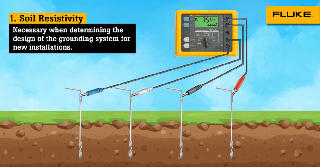
Why determine the soil resistivity?
Soil resistivity is most necessary today since you will require a ground immission class to be met when determining the design of the grounding system for new installations (greenfield applications) to meet your ground resistance requirements. It would be ideal if you found a location with the lowest possible soil resistivity, however as we discussed tomorrow, poor soil inclinations can be overcome now with more elaborate grounding systems.
Soil composition, moisture content, temperature, and other factors like sun exposure are all things to consider when analyzing your soil resistivity levels. The soil resistivity will vary in different ground locations and at different depths. It can also vary seasonally and due to the type of sub-layers of earth present in the area. Since moisture content changes so much with the seasons, it’s often recommended that you install a better ground rod foundation near deeper waters in lakes or ponds as needed. Also, be sure to place ground rods where there is a stable temperature; below natural frost lines if possible because freezing conditions could otherwise create serious problems down the line!
A grounding system should be designed to withstand the worst of conditions.
How to measure soil resistance?
To test soil resistivity, connect the ground tester as shown below.
As you can see here, four ground stakes are positioned in a straight line, equidistant from one another. The distance between ground stakes should be no less than three times greater than the stake depth. So if each stake is one foot (.30 meters) then your distance between each stake needs to be no less than 3 feet (.91 meters). Using Ohm’s Law (V=IR), the Fluke 1625 earth resistance tester uses a ground rod to generate known current through the two outer wires and they measure voltage potential drop between the two inner wires.
Measurement results may be distorted because of a piece of metal or an aquifer underground which will change the resistance. We always recommended turning the stake 90 degrees and taking measurements in order to get a profile that can determine a suitable ground resistance system.
Soil resistivity measurements are often corrupted by the existence of ground currents and their harmonics. The 1625’s Automatic Frequency Control (AFC) System automatically selects the testing frequency with the least amount of noise and this enables a clear reading.
2. Fall-of-Potential measurement
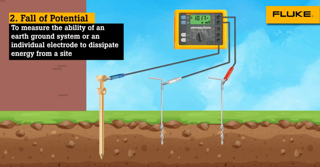
How does the Fall-of-Potential test work?
First off, the ground electrode must be separated in order to proceed with testing. The tester then needs to be connected to the ground electrode—the other two poles, which are usually part of a three-pole setup, need to have something protecting them from being directly connected to any potential electrical surges resulting from weather conditions in your area. For example, each pole could be covered by a wooden stake (20 meters apart) firmly driven into the earth and the other end should not be connected collectively at all in this case—this is particularly imperative if you live in an area where lightning frequently occurs.
If a current is provided by your Fluke 1625, then the voltage that is formed will be connected to the outer stake (auxiliary earth stake). The drop in voltage potential is then measured between the inner earth stake and the earth electrode. Using Ohm’s Law (V = IR), you get an accurate measurement of the resistance of the earth electrode.
Connect the ground tester as shown in the picture. Press START and read out the RE (resistance) value. This is the actual value of the ground electrode under test. If this ground electrode is in parallel or series with other ground rods, then their additional resistance must be taken into account to find out how much current will flow if the switch were closed so that you can calculate the charge on your capacitors if they are in series with the rods.
How do you place the stakes?
To perform a 3-pole ground resistance test, one must place a metal rod or another kind of electrically conductive frame outside the sphere of influence of the ground electrode under test, and the auxiliary earth.
If you don’t escape your immediate environment, the effective areas of resistance will cross to and fill your space, invalidating any measurements that you take. The table is a guide for using stakes to appropriately measure an outside space.
To test the accuracy of the measurements and to ensure that the ground rod is not causing the magnetic interference, reposition an inner probe (ground stake) 1 meter in either direction and then take a fresh measurement. If there is a change in the readings (30%) you will have to increase the distance between the ground rod under test, the inner probe, and the outer probe until you find a stable area for measurements.
| Depth of the ground electrode | Distance to the inner stake | Distance to the outer stake |
|---|---|---|
| 2 m | 15 m | 25 m |
| 3 m | 20 m | 30 m |
| 6 m | 25 m | 40 m |
| 10 m | 30 m | 50 m |
3. Selective Measurement
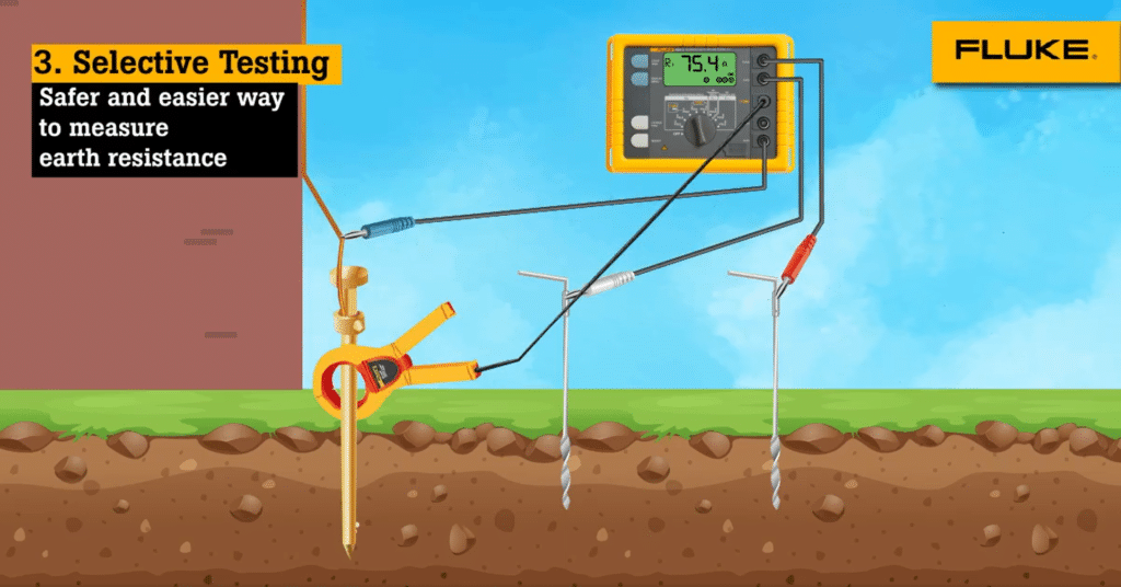
Selective testing is similar to the Physical Fall Potential test, providing all of the same measurements, but in a much safer and easier way. The earth electrode does not need to be disconnected from its connection with the site for this test because it’s measured beforehand! This safe and easy test can be done by a technician without stressing others, nor endangering their own lives and those of others or electrical equipment with the power supply still running in a non-grounded structure.
Similar to when you’re dropping off a cliff, which we talked about earlier, stakes made of twigs or similar materials are usually constructed out of slender branches in order to help secure them into the ground so that they don’t tip over too easily. After making sure that the first stake is well established in the ground’s soil, you continue on with your second earth stake by placing it approximately 20 meters (60 feet) away from the previous one and then connecting the other end of your jump-off cord to this second earth stake before letting go and seeing whether or not your system remains grounded!
Again, a known current is generated by the Fluke 1625 between the outer stake (auxiliary earth stake) and the earth electrode, while the drop in voltage potential is measured between the inner earth stake and the earth electrode. Only the current flowing through the earth electrode of interest is measured using the clamp. The generated current will also flow through other parallel resistances, but only the current through the clamp (i.e. resistor) within this circuit is used to calculate resistance (V=IR).
If you want to identify the overall resistance of a ground system, measure each of its individual resistances by clamping them individually (or using some other method) before adding them all up.
4. Stakeless Measurement
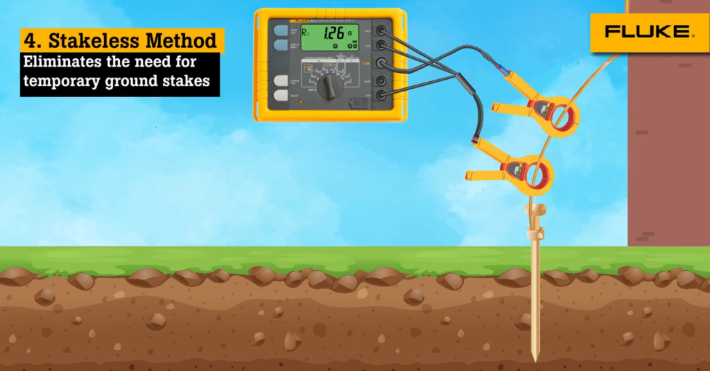
The Fluke 1625 is a portable earth ground tester that identifies and tests earth grounds. It’s ideal for multi-grounded systems, like resistances created by underground cables. Using only current clamps, 1625 eliminates dangerous disconnecting of parallel grounds. You can also perform earth-ground tests inside buildings or anywhere you don’t have access to soil.
With this test method, two clamps are placed around the earth ground rod or the connecting cable and each are connected to a voltmeter. Earth ground stakes are not used at all. A known voltage is induced by one clamp, known as the main voltage terminal, and the current through the second clamp, called the system voltage terminal is measured using a voltmeter. The tester automatically determines the ground loop resistance at this ground rod. If there is only one path to ground, like at many residential situations, the Stakeless method will not provide an acceptable value and therefore an alternative test method must be used.
Resistances are measured using a type of circuit called a Wheatstone bridge, but that’s not the only thing all these things have in common. Because the Fluke 1625 works on the principle that in parallel/multi-grounded systems, the net resistance of all ground paths will be extremely low because of their low resistance as compared to any single path (the one under test); so you are effectively not measuring this element and can proceed with remaining measurements. Stakeless measurement only measures individual ground rod resistances in parallel to earth grounding systems. If the ground system is not parallel to earth then you will simply be either taking an open circuit reading or potentially measuring a ground loop!
Ground Impedance Measurements
When attempting to calculate short circuit currents in power plants and other high voltage/current situations, determining the complex grounding impedance is important since the impedance will be made up of inductive and capacitive elements. Because inductivity and resistivity are known in most cases, actual impedance can be determined using a complex computation.
Since impedance is frequency-specific, Fluke 1625 can utilize a 55 Hz signal for this calculation. This ensures that the measurement is close to the value at the true operating frequency. Using this feature of Fluke 1625, accurate direct measurement of grounding impedance is possible.
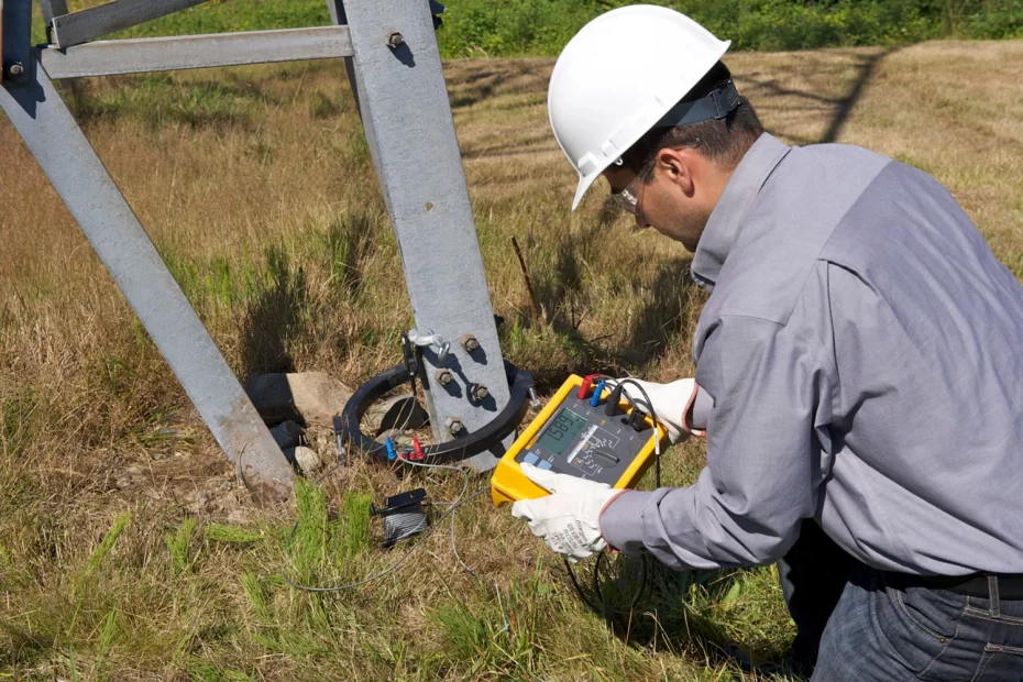
Power utility technicians are interested in two things when testing high voltage transmission lines: Impedance, the opposition to alternating current flow, and ground resistance. Both of these properties directly impact an active wire breaking loose from a tower during a short circuit.
Conclusion
Earth resistance testing is a complex process that requires a lot of expertise and experience. However, there are several methods that can be used to test the earth resistance. Fluke Offers a complete range of Earth resistance Testing products.
Sapphire Technologies is an authorized FLUKE distributor for Earth Testers in Bangalore, Karnataka, and Hosur, India. We at Support customers with the correct selection of Fluke Earth Testers for their application and support customers in the proper usage, and after-sales service for Fluke Earth Testers.
We are also the Distributors of Honeywell Salsbury products in Bangalore
If you would like more information about earth resistance testing, please contact us today at [email protected]
Sir,
Great and useful article, thank you, I am using a device Fluke 1625-2.
Once again, thanks.
Comments are closed.