Sapphire Technologies, a Fluke Distributor in Karnataka aims to help customers with the latest tools and techniques in electrical tests and measurements to keep their equipment’s running smoothly without disruption. This article talks about the Earth Resistance testing techniques.
Ground can be an important aspect of your electrical service when it comes down to how effectively current flows, but if the path isn’t clear or if there are other issues with the overall system, that’s not good, and having contractors who address all necessary repairs is even better.
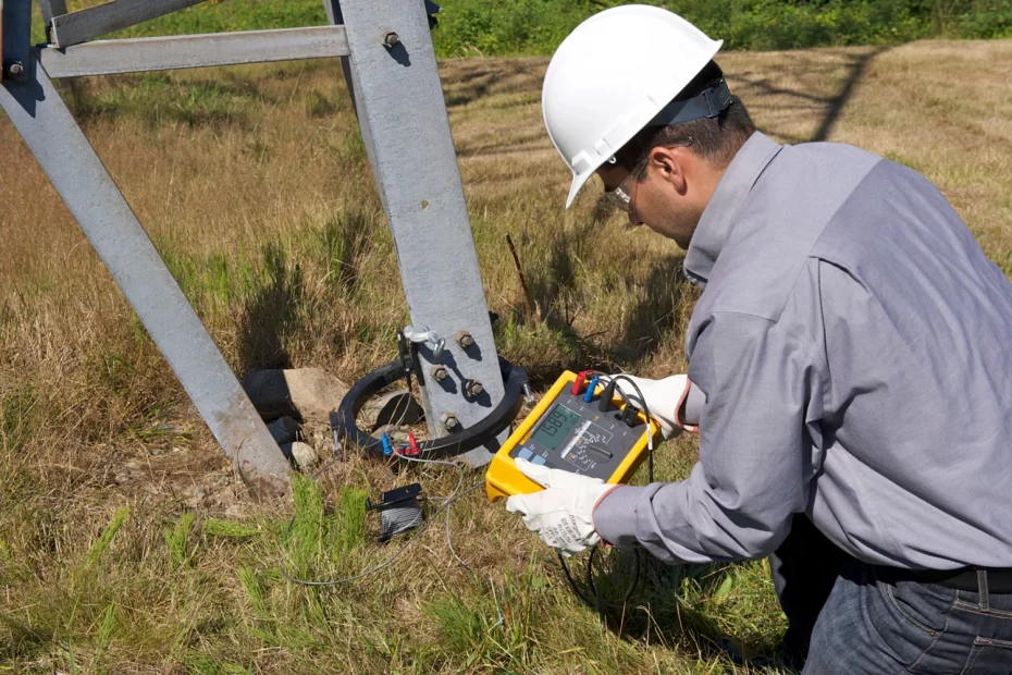
There are a few different ways for performing a ground resistance test depending on the client’s needs. The standard allows for three earth resistance test techniques.
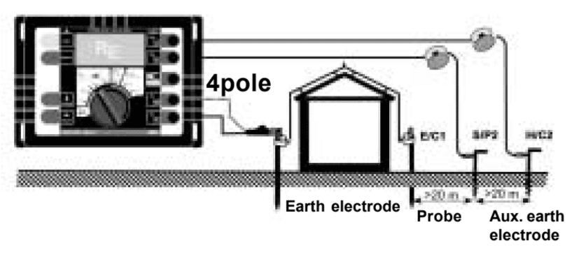
Practical Earth Resistance Testing setup
In a practical earth test, temporary earth stakes are used, one stake usually noted as H or C2 is used as a path for test current which is injected into the earth system under consideration.
The second stake which is usually noted as S or P2 measures the potential developed by the injection of the test current.
A nominal distance of 20m between the stakes is recommended. This will vary depending on the nature of the system under test.

1. 3pole- and 4pole-measurements
The standard earth test, usually called the ‘Fall of Potential Method’ uses either 3 or 4 poles or connections. The four pole method compensates for any voltage drop there may be in the wire used to connect to the earth E under test. The fourth wire is particularly important if the connection to the E is a long distance from the instrument.

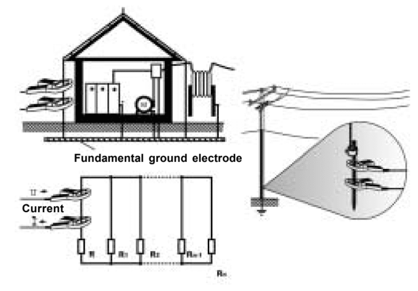
2. Selective measurement method
Selective earth testing is based on the standard ‘Fall of Potential Method’ but has the advantage that the earth system does not need to be disconnected. The E point is connected to the instrument; a current transformer is used to measure the test current through ‘selective’ parts of the earthing system. If there are parallel paths in the earthing system the individual earth resistances of these parallel earths can be measured.

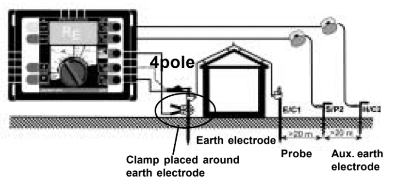
3. Stakeless measurement method
In this method, the temporary stakes are replaced by two current clamps. The test current from the E and the H/C2 terminals of the instrument is fed through a current clamp. This clamp is placed around the conductor connecting the earth under test. A second measuring clamp is placed around the same conductor.
The resulting measurement is that of the earth under consideration with a series element which is the combined parallel resistance of all other connected elements. As the combined resistance of the parallel paths is small compared to the resistance of the earth is measured. Clamps should be at least 10 cm apart.

Conclusion
Fluke 1625 & Fluke 1623 are the most reliable Earth Resistance Testers in the market. Sapphire Technologies is an authorized FLUKE distributor for Earth Testers in Bangalore, Karnataka, and Hosur, India. We support customers with the correct selection of Fluke Earth Testers for their application and support customers in the proper usage, and after-sales service for Fluke Earth Testers.
To Know more about Fluke Earth Testers and Other Fluke Products like Fluke Power Quality Analysers, Fluke Thermal Imagers, etc reach out to us at info@sapphire-tech.com
You Can also visit our Website www.Sapphire-Tech.com for details of the Complete Fluke products.
We are also the Distributors of Honeywell Salsbury products in Bangalore
